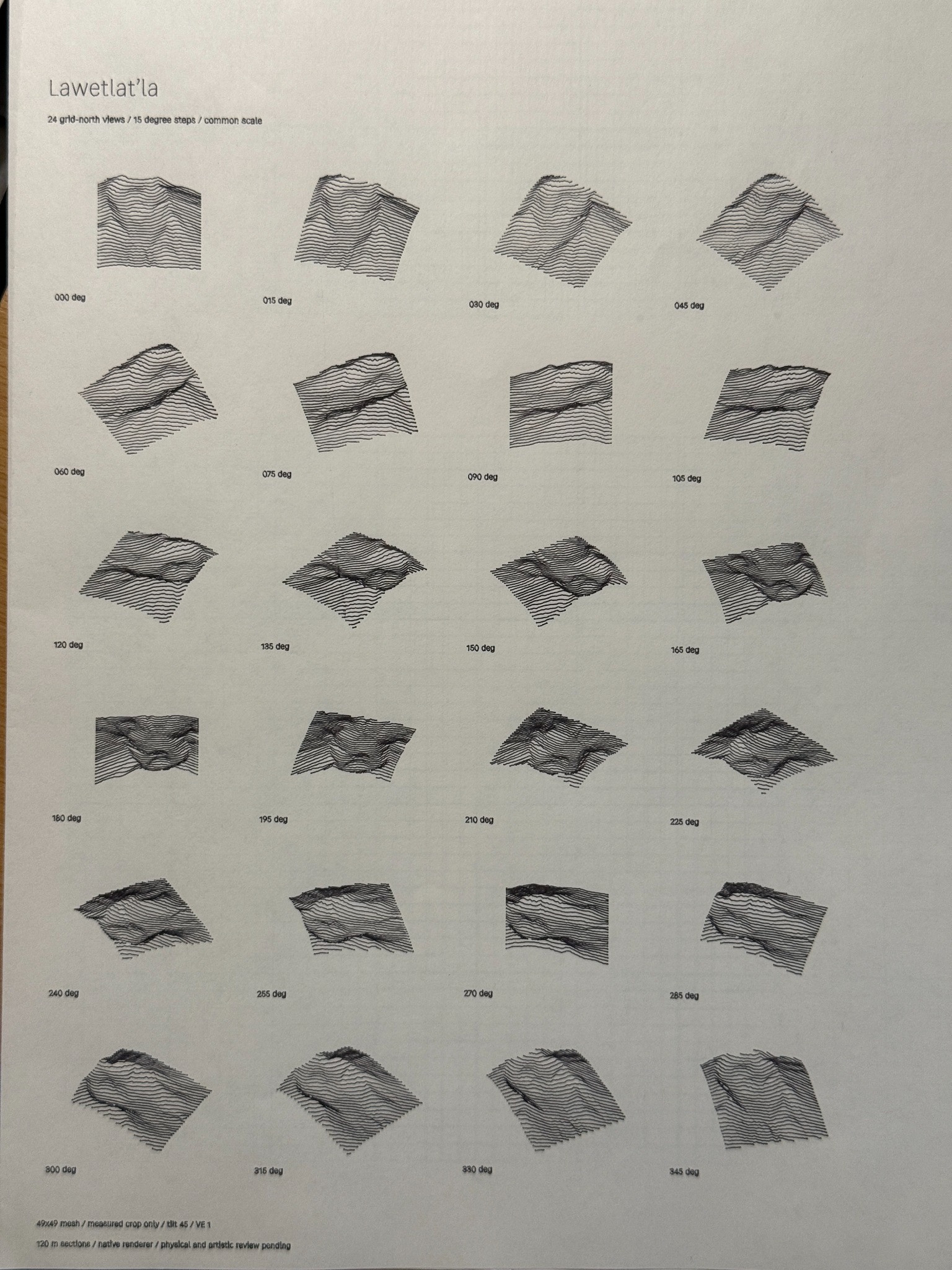
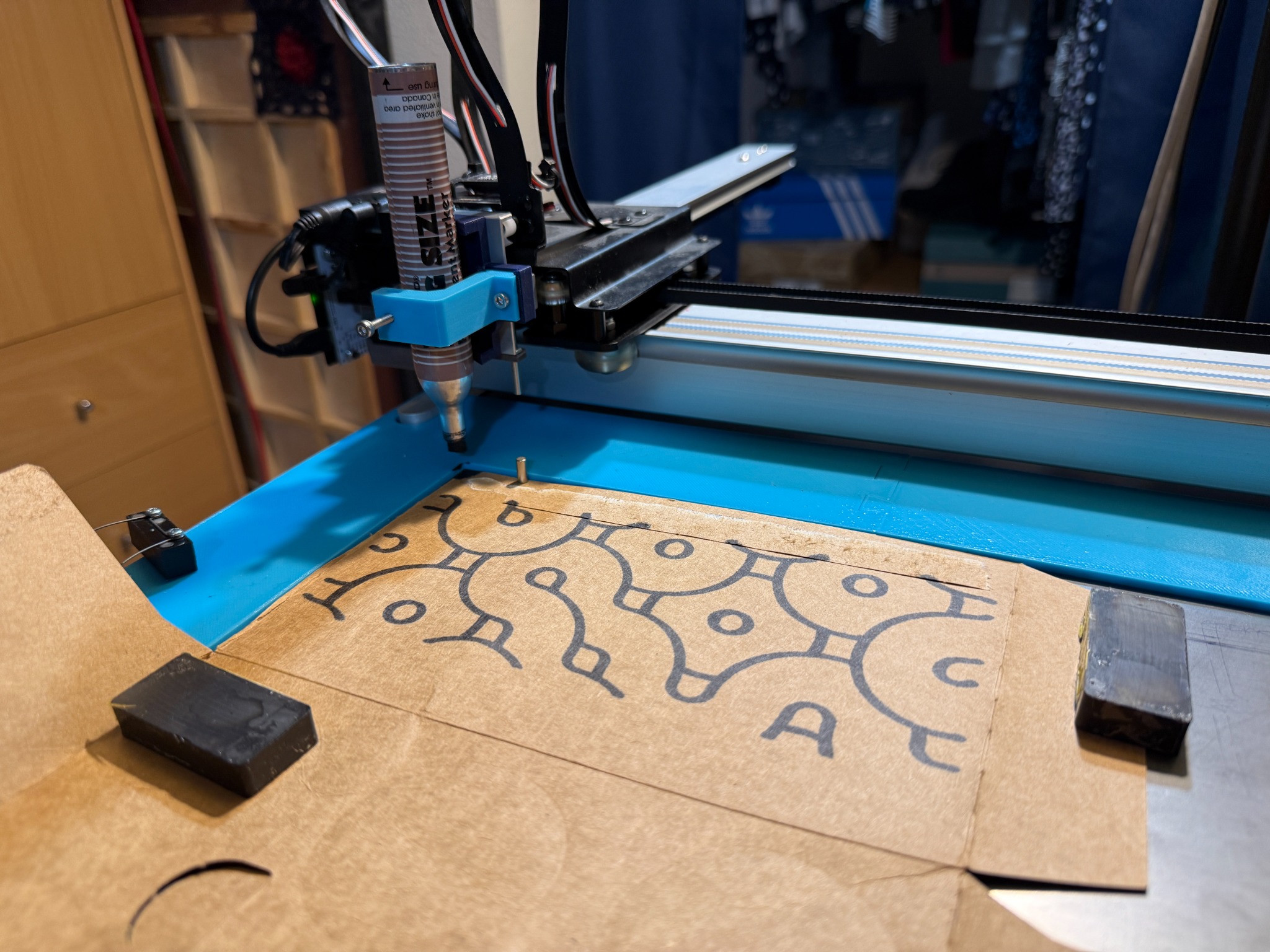
I wanted a repeatable place to set the paper on my AxiDraw. A small shift at the corner can make a border uneven or leave a title too close to the edge, especially on a postcard.
This paper margin jig grew out of that problem. I used text-to-CAD to turn measurements and requested changes into an editable model, then printed and checked it against the machine. The useful part of the process was being able to revise a specific dimension without starting the design over.
Starting with the machine
The jig locates against the AxiDraw V3’s extended outrigger struts. Two open, U-shaped pockets slide around the struts, while a long crossbar and a perpendicular rail give the paper a square corner to sit against.
The starting measurements were 419 mm across the outside of the struts and 386 mm between their inside edges. Those measurements gave us a nominal strut width of 16.5 mm. The model added a small fit allowance, making each pocket 17.1 mm wide.
Physical prints supplied the corrections. The first pockets were too shallow, so their depth increased from 18 to 38 mm. A two-half fit then left a 2.6 mm gap at the center when both ends were seated. That gap was added to the span. The long rail eventually reached 250 mm, providing support along more of the paper edge.
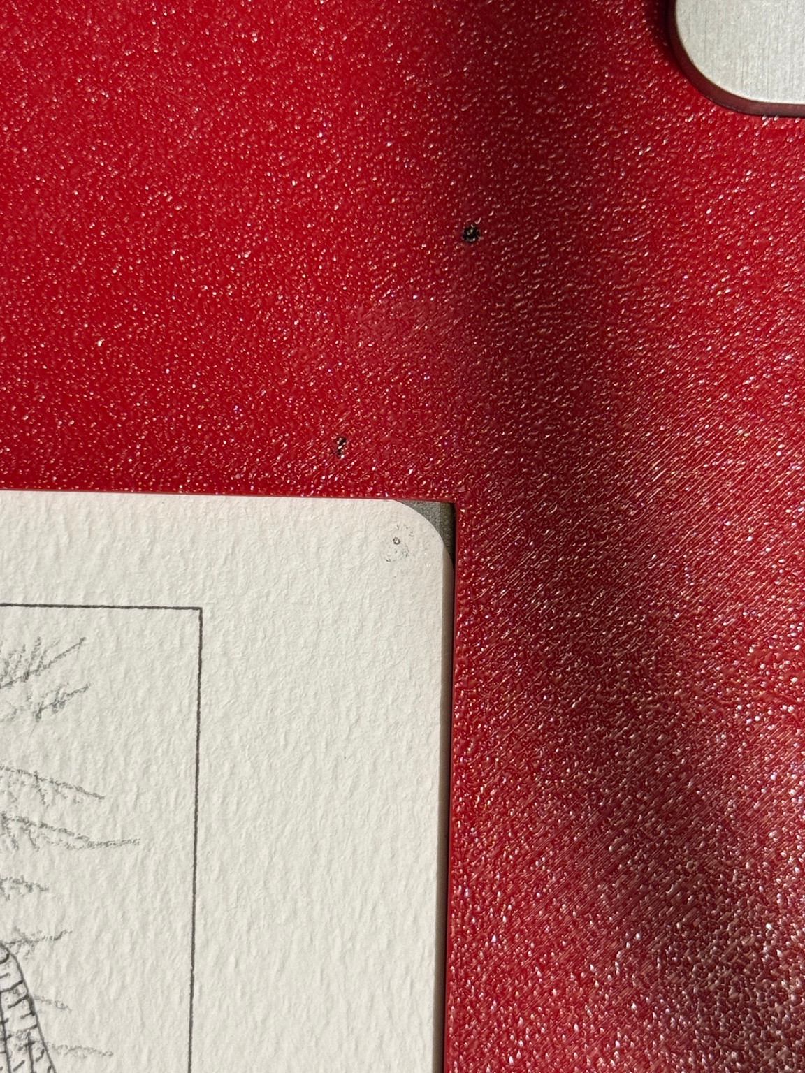
The earlier printed jig at the paper corner, before the final 3 mm / 5 mm correction. In this photo, the card’s top edge is at the right.
A small test before a full reprint
Later, a placement check showed that the paper corner still needed a 3 mm adjustment at the left stop and 5 mm at the top stop. We first made a removable L-shaped insert: 30 × 30 mm overall and only 1.5 mm high. It was a quick way to test the correction while keeping the original jig.
The insert brought the marks much closer to their intended position. I still saw about 1 mm of difference at the bottom and suspected the short insert was not bracing enough of the card. That was a working explanation, not a confirmed cause.
Rather than make another small insert, I asked to put the same 3 mm and 5 mm correction into the full-size version.
The two-piece v0.7 revision
In the CAD model, the inside paper corner moved from (57, 55) to (60, 60) mm. The outrigger pockets stayed where they were. We kept the fitted overall width of 433.6 mm, the 250 mm rail reach and the 3 mm thickness. We did not add another correction for the remaining 1 mm.
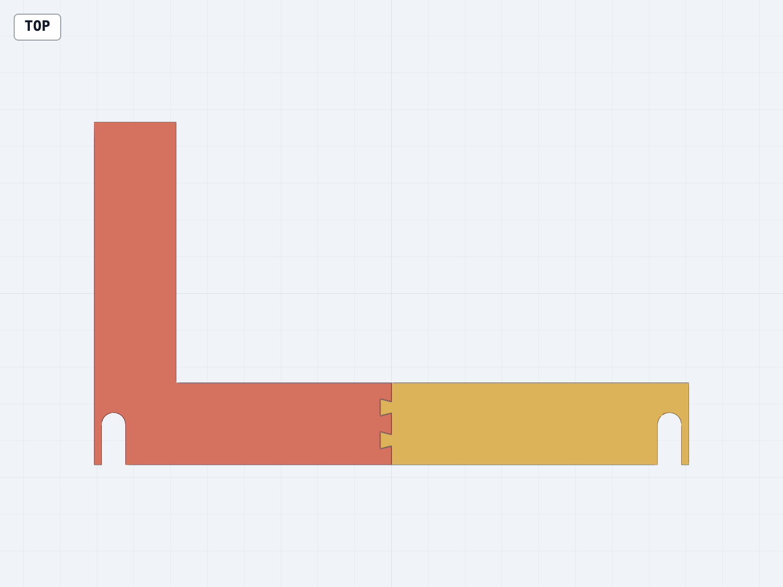
Top view of the v0.7 CAD assembly. The colors distinguish the two printable halves, not filament choices.
The revised model was split into two printable halves with two dovetail keys at the center. The keys lower into their matching sockets from above. A dry fit on a flat surface comes before gluing, with a straightedge against the paper-contact edge to keep both halves aligned.
- Full assembled footprint: 433.6 × 250 mm.
- Long half: 216.8 × 250 × 3 mm.
- Short half: 224.8 × 60 × 3 mm, including its keys.
- Files: editable CAD source, STEP references and separate STL files for printing.
The parts were designed to print flat without supports. The model’s geometry checks passed, but the physical print still had to establish fit, joint clearance and clearance around the pen carriage. The separate test shim is left out when using this revised jig because its correction is already built in.
Checking it on paper
After printing the full-size revision, I ran the placement test again on a 152 × 100 mm card. The red pass was made with the new jig over the earlier black pass. The blue handwritten numbers record my measured distances from the card edges.
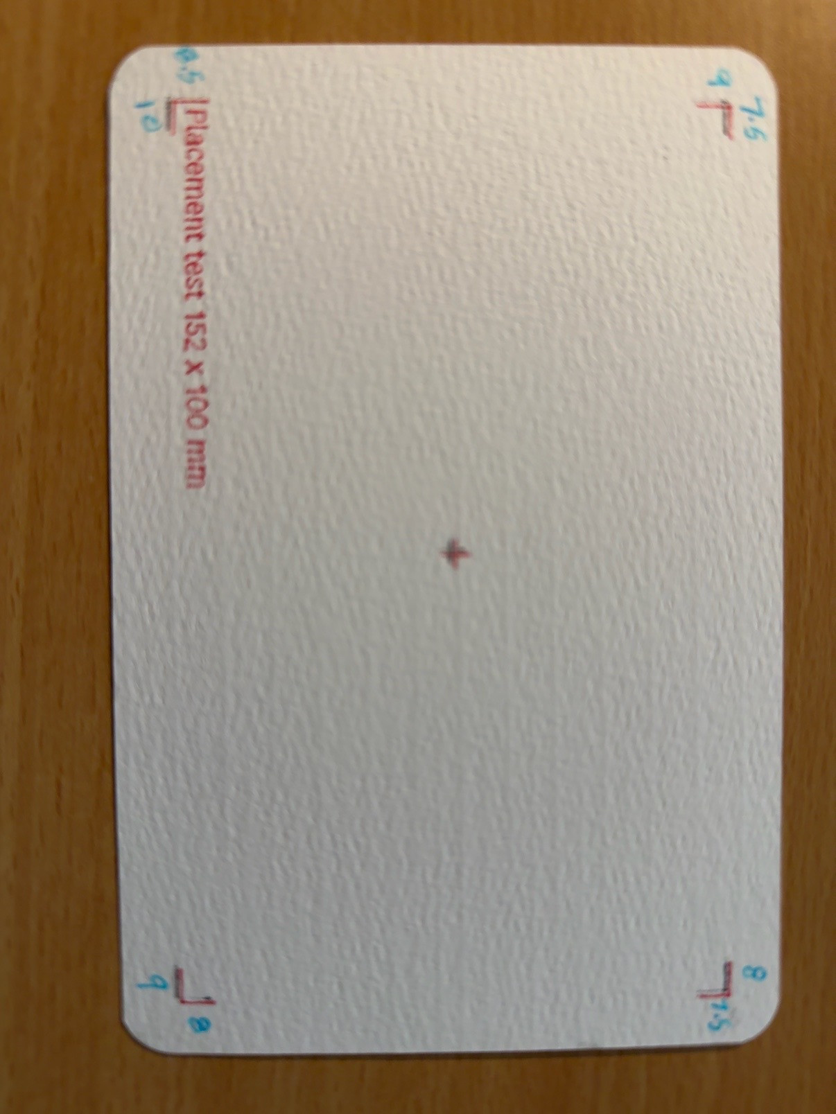
The new-jig pass is red, the earlier pass is black, and the measured distances from the card edges are written in blue.
The result was close enough for my work. I was comfortable with roughly half a millimeter to a millimeter of remaining variation, which could also involve the cards or how they were seated. That is my acceptance of this setup, not an accuracy specification for the plotter.
For a future 9 × 12 inch drawing, that amount is unlikely to matter after matting and framing. For the smaller cards, I still leave enough room around the border and title.
Text-to-CAD made the revisions manageable. Measuring the machine, printing the part and checking the marks on paper were what told us whether those revisions helped.